Improved reconstructed velocity maps by means of alignment strategy No. 1#
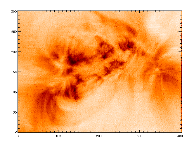
Reconstructed Intensity map (source: TRACE 195A)
Reconstructed Velocity maps:#
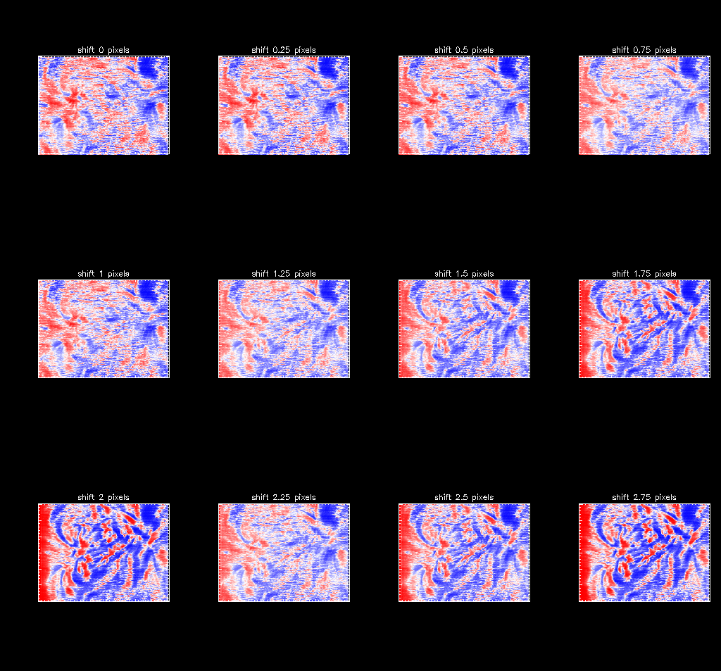
1. Image showing the reconstructed velocity maps from the I_plus images with 0 -- 2.75 pixels shifts
3. Result from the 0-pixel shifted I_plus image (source: EIS 40 slot image 195A)
![]()
4. Result from the 0.25-pixels shifted I_plus image (source: EIS 40 slot image)
![]()
5. Result from the 0.5-pixels shifted I_plus image (source: EIS 40 slot image)
![]()
6. Result from the 0.75-pixels shifted I_plus image (source: EIS 40 slot image)
![]()
7. Result from the 1.0-pixels shifted I_plus image (source: EIS 40 slot image)
![]()
8. Result from the 1.25-pixels shifted I_plus image (source: EIS 40 slot image)
![]()
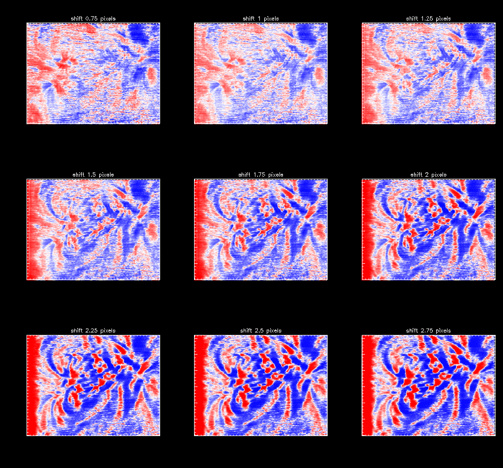
Reconstructed velocity maps by means of alignment strategy No. 2#
1. Image showing the reconstructed velocity maps from the I_plus images with 0.75 -- 1.25 pixels shifts
2. Result from the 0.75-pixels shifted I_plus image (source: EIS 40 slot image)
![]()
3. Result from the 1.0-pixels shifted I_plus image (source: EIS 40 slot image)
![]()
4. Result from the 1.25-pixels shifted I_plus image (source: EIS 40 slot image)
![]()
